Introduction
GPIO (General Purpose Input Output) pins can be used as input or output and allows raspberry pi to connect with general purpose I/O devices.
- Raspberry pi 3 model B took out 26 GPIO pins on board.
- Raspberry pi can control many external I/O devices using these GPIO’s.
- These pins are a physical interface between the Pi and the outside world.
- We can program these pins according to our needs to interact with external devices. For example, if we want to read the state of a physical switch, we can configure any of the available GPIO pins as input and read the switch status to make decisions. We can also configure any GPIO pin as an output to control LED ON/OFF.
- Raspberry Pi can connect to the Internet using on-board Wi-Fi or Wi-Fi USB adapter. Once the Raspberry Pi is connected to the Internet then we can control devices, which are connected to the Raspberry Pi, remotely.
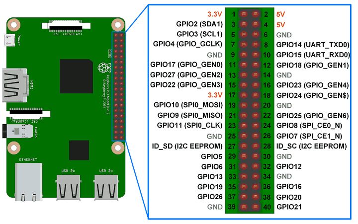
GPIO Pins of Raspberry Pi 3 are shown in below figure:
Some of the GPIO pins are multiplexed with alternate functions like I2C, SPI, UART etc.
We can use any of the GPIO pins for our application.
Pin Numbering
We should define GPIO pin which we want to use as an output or input. But Raspberry Pi has two ways of defining pin number which are as follows:
- GPIO Numbering
- Physical Numbering
In GPIO Numbering, pin number refers to number on Broadcom SoC (System on Chip). So, we should always consider the pin mapping for using GPIO pin.
While in Physical Numbering, pin number refers to the pin of 40-pin P1 header on Raspberry Pi Board. The above physical numbering is simple as we can count pin number on P1 header and assign it as GPIO.
But, still we should consider the pin configuration diagram shown above to know which are GPIO pins and which are VCC and GND.
Interfacing Diagram

Example
Now, let’s control LED using switch connected to the Raspberry Pi. Here, we are using Python and C (WiringPi) for LED ON-OFF control.
Control LED using Python
Now, let’s turn ON and OFF an LED using Python on Raspberry Pi. Switch is used to control the LED ON-OFF.
Python Program
import RPi.GPIO as GPIO #import RPi.GPIO module
LED = 32 #pin no. as per BOARD, GPIO18 as per BCM
Switch_input = 29 #pin no. as per BOARD, GPIO27 as per BCM
GPIO.setwarnings(False) #disable warnings
GPIO.setmode(GPIO.BOARD) #set pin numbering format
GPIO.setup(LED, GPIO.OUT) #set GPIO as output
GPIO.setup(Switch_input, GPIO.IN, pull_up_down=GPIO.PUD_UP)
while True:
if(GPIO.input(Switch_input)):
GPIO.output(LED,GPIO.LOW)
else:
GPIO.output(LED,GPIO.HIGH)
Functions Used:
RPi.GPIO
To use Raspberry Pi GPIO pins in Python, we need to import RPi.GPIO package which has class to control GPIO. This RPi.GPIO Python package is already installed on Raspbian OS. So, we don’t need to install it externally. Just, we should include library in our program to use functions for GPIO access using Python. This is given as follows.
import RPi.GPIO as GPIO
GPIO.setmode (Pin Numbering System)
This function is used to define Pin numbering system i.e. GPIO numbering or Physical numbering.
In RiPi.GPIO GPIO numbering is identified by BCM whereas Physical numbering is identified by BOARD
Pin Numbering System = BOARD/BCM
E.g. If we use pin number 40 of P1 header as a GPIO pin which we have to configure as output then,
In BCM,
GPIO.setmode(GPIO.BCM)
GPIO.setup(21, GPIO.OUT)
In BOARD,
GPIO.setmode(GPIO.BOARD)
GPIO.setup(40, GPIO.OUT)
GPIO.setup (channel, direction, initial value, pull up/pull down)
This function is used to set the direction of GPIO pin as an input/output.
channel – GPIO pin number as per numbering system.
direction – set direction of GPIO pin as either Input or Output.
initial value – can provide initial value
pull up/pull down – enable pull up or pull down if required
Few examples are given as follows,
- GPIO as Output
GPIO.setup(channel, GPIO.OUT)
- GPIO as Input
GPIO.setup(channel, GPIO.IN)
- GPIO as Output with initial value
GPIO.setup(channel, GPIO.OUT, initial=GPIO.HIGH)
- GPIO as Input with Pull up resistor
GPIO.setup(channel, GPIO.IN, pull_up_down = GPIO.PUD_UP)
GPIO.output(channel, state)
This function is used to set the output state of GPIO pin.
channel – GPIO pin number as per numbering system.
state – Output state i.e. HIGH or LOW of GPIO pin
e.g.
GPIO.output(7, GPIO.HIGH)
GPIO.input(channel)
This function is used to read the value of GPIO pin.
e.g.
GPIO.input(9)
Control LED using C (WiringPi)
We can access Raspberry Pi GPIO using C. Here, we are using WiringPi library for accessing Raspberry Pi GPIO using C.
Before implementing LED blinking using wiringPi, you can refer How to use WiringPi library.
Program
#include
#include
int LED = 26; /* GPIO26 as per wiringPi, GPIO12 as per BCM, pin no.32 */
int switch_input = 21; /* GPIO21 as per WiringPi, GPIO5 as per BCM, pin no.29 */
int main(){
wiringPiSetup(); /* initialize wiringPi setup */
pinMode(LED,OUTPUT); /* set GPIO as output */
pullUpDnControl(switch_input, PUD_UP);
while (1){
if(digitalRead(switch_input))
digitalWrite(LED,LOW); /* write LOW on GPIO */
else
digitalWrite(LED, HIGH); /* write HIGH on GPIO */
}
}
